
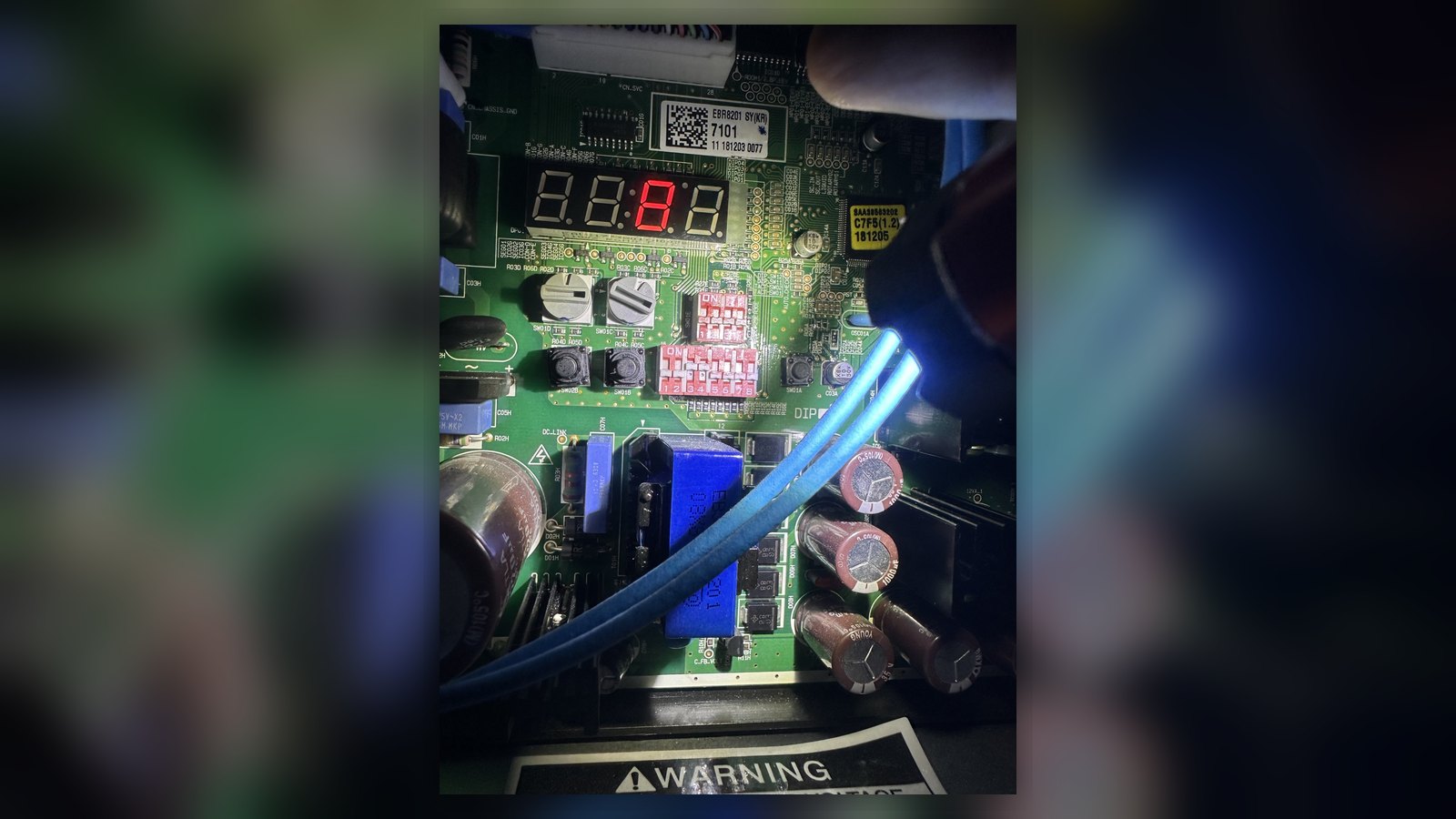
System: LG Multi V 5 Heat Recovery, 12-ton, 460V/3Ph
Configuration: 1 outdoor unit, 9 indoor units, 3 heat recovery boxes
Location: Commercial building, Los Angeles area
Service: Advanced VRF diagnostics following two unsuccessful repair attempts
The Situation
PARUS HVAC Services was called to diagnose an LG Multi V 5 heat recovery VRF system that had been out of normal operation for an extended period.
Two previous repair attempts had not returned the system to service.
The service history included:
- Compressor No. 2 had failed and was replaced. The system was charged but still would not start normally.
- The inverter PCB serving Compressor No. 1 had subsequently been diagnosed as faulty and replaced, but the overall problem remained.
- The outdoor unit was reporting Error 2001.
- The system could not detect any of its 9 indoor units or 3 heat recovery boxes.
- Attempts to perform the pipe configuration procedure showed zero indoor units and zero HR boxes.
At that point, the system appeared to have both a communication problem and an unresolved mechanical/electrical fault.
Diagnostic Approach
Rather than continuing to replace components based only on displayed fault codes, troubleshooting began with the manufacturer’s service documentation for the specific Multi V generation and live operating data from the system.
Understanding Error 2001
On this Multi V 5 system, Error 2001 was associated with an unsuccessful auto pipe search procedure.
That distinction was important because pipe configuration cannot be completed correctly until the required indoor-unit addressing process has been completed.
The failure therefore did not automatically indicate a defective communication board or failed network.
Verifying the Communication Network
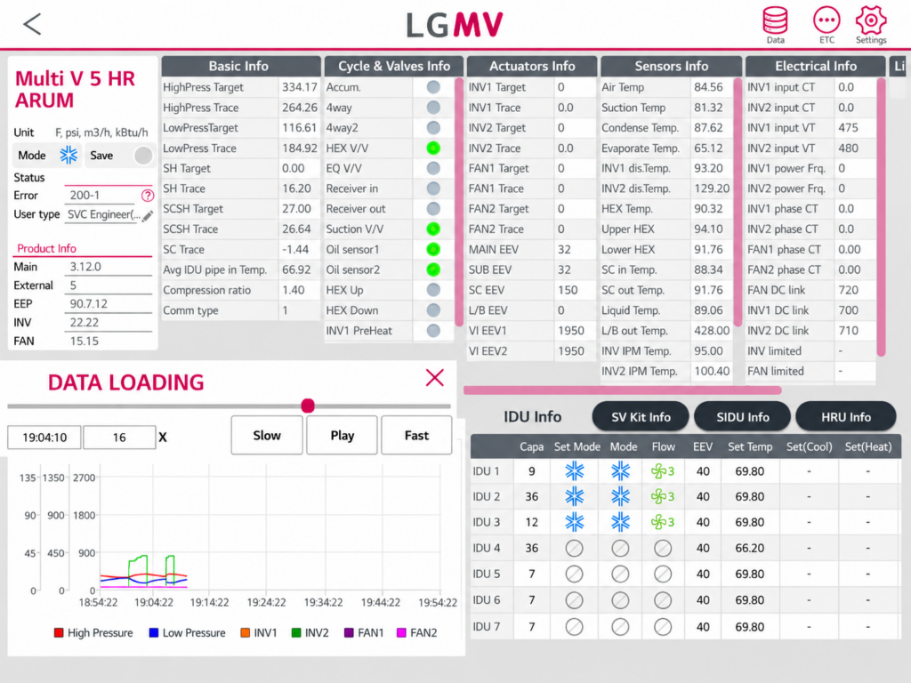
Live monitoring showed communication counters incrementing at the indoor units.
This confirmed that communication traffic was present and provided strong evidence that:
- the RS-485 communication network was active;
- the outdoor unit communication circuit was operating;
- the system was not dealing with a completely failed communication bus.
This allowed the diagnostic process to move away from unnecessary control-board replacement and toward the conditions preventing successful addressing.
Checking Addressing Prerequisites
The manufacturer’s procedure requires the indoor units to be powered and the wired controllers to be in the required state before auto addressing can be completed.
One indoor unit could not initially be switched off from its controller. Its temperature setting was approximately 20°F below room temperature while operating in Auto mode, causing it to remain continuously active.
That single condition prevented the addressing procedure from completing normally.
After correcting the indoor-unit condition and power-cycling the heat recovery boxes, auto addressing completed successfully on the first attempt.
The outdoor unit then recognized:
9 indoor units
3 heat recovery boxes
The stored pipe-to-valve configuration was subsequently checked multiple times and remained stable.
No control boards were replaced to restore communication.
Compressor Electrical Testing
With the communication issue isolated, the compressors were electrically tested.
Compressor No. 1 was found shorted to ground.
This was particularly important because the inverter PCB driving that compressor had already failed and had been replaced during previous work.
A compressor with compromised winding insulation can place the inverter power electronics at risk. Therefore, replacing an inverter board without verifying the condition of the compressor it drives can leave the underlying problem unresolved.
In this case, the compressor required replacement before normal system operation could be restored.
Additional Findings
Liquid Bypass Temperature Sensor
Live data also identified a temperature sensor on the liquid bypass circuit displaying a full-scale abnormal value during three separate data captures.
Because this circuit is involved in system protection and refrigerant management, the sensor requires further verification before commissioning the system with a replacement compressor.
Compressor No. 2 and Oil Condition
Compressor No. 2 had recently been installed while the system still contained the failed Compressor No. 1.
For that reason, the condition of the refrigerant and oil became an important part of the repair strategy.
If the original compressor failure resulted in acid contamination or a motor burnout condition, the recently installed compressor and the rest of the refrigerant circuit could potentially be exposed to contaminated oil and refrigerant.
Rather than assume contamination, the repair plan calls for testing first.
Repair Plan
A phased repair approach was provided to the customer.
The first stage includes:
- recover and weigh the refrigerant charge;
- remove the failed Compressor No. 1;
- evaluate the compressor/oil condition;
- perform an acid test;
- inspect the refrigerant circuit;
- determine the appropriate cleanup procedure.
The acid-test result becomes the decision point.
If no significant acid contamination is found
Proceed with the standard compressor replacement procedure, pressure testing, evacuation, recharge and commissioning.
If acid contamination is confirmed
Additional burnout-cleanup procedures can be performed, including appropriate filtration and follow-up system testing.
This approach prevents the customer from paying for extensive decontamination work unless testing shows that it is actually required.
Outcome of the Diagnostic Visit
The communication problem was resolved during the diagnostic visit.
The LG Multi V system successfully recognized all:
9 indoor units
3 heat recovery boxes
The communication network, addressing status and stored configuration were verified.
The separate mechanical/electrical fault was then isolated to Compressor No. 1, which tested shorted to ground.
Rather than leaving the system operating under temporary or abnormal conditions, the unit was shut down by agreement pending mechanical repair.
The customer received a defined repair plan that separates the standard compressor replacement from any additional cleanup work that may become necessary after oil testing.
What This Case Demonstrates
Error Codes Are a Starting Point
An error code identifies a condition detected by the control system. It does not necessarily identify the component that caused it.
In this case, the pipe-search failure was caused by an unmet procedural prerequisite rather than a failed communication board.
Manufacturer Procedures Matter
VRF commissioning procedures are sequential.
Addressing, equipment detection, pipe configuration and commissioning must be performed in the correct order. Skipping a prerequisite can create additional faults that resemble hardware failures.
Live VRF Data Can Prevent Unnecessary Parts Replacement
Communication counters, sensor readings, valve status and system configuration data can establish what parts of the system are functioning before components are replaced.
Here, live data helped demonstrate that the communication network itself was operating.
Electrical Testing Should Be Part of Inverter Diagnostics
When an inverter PCB associated with a compressor has failed, the compressor should also be electrically evaluated before the replacement inverter is put into service.
In this case, Compressor No. 1 was found shorted to ground.
Sequential Compressor Failures Require Investigation
When multiple major components fail on the same refrigerant circuit, simply replacing the next failed component may not be enough.
Oil condition, contamination, refrigerant circuit condition and the cause of the previous failure should be evaluated before commissioning another replacement compressor.
Need Help With an LG Multi V or VRF System?
PARUS HVAC Services provides advanced troubleshooting, diagnostics and repair for LG Multi V, Mitsubishi City Multi, Daikin VRV and other commercial VRF systems throughout Los Angeles and Ventura County.